There is a particular kind of afternoon that anyone who owns a 3D printer knows. You need a bracket. Not an interesting bracket — a flat plate with two holes at a spacing you measured with calipers, and a lip so it does not slide. It should take ten minutes.
Instead you open a CAD program you use four times a year, spend the first twenty minutes remembering how sketches and constraints work, and the next forty discovering that the hole you placed is driven by a dimension you set before you knew what it was for. Eventually you export an STL, slice it, print it, and find out the wall is too thin where it matters. The part was never hard. The software was.
What changed
1DesignTool 1.14.0 adds a CAD parts workspace, in preview. Now you can describe a part in millimetres, watch it get modelled parametrically, pull its dimensions around in a live 3D view, and run it through a gate that tells you what it checked and — just as usefully — what it could not.
How it works in practice
Describe the part in millimetres
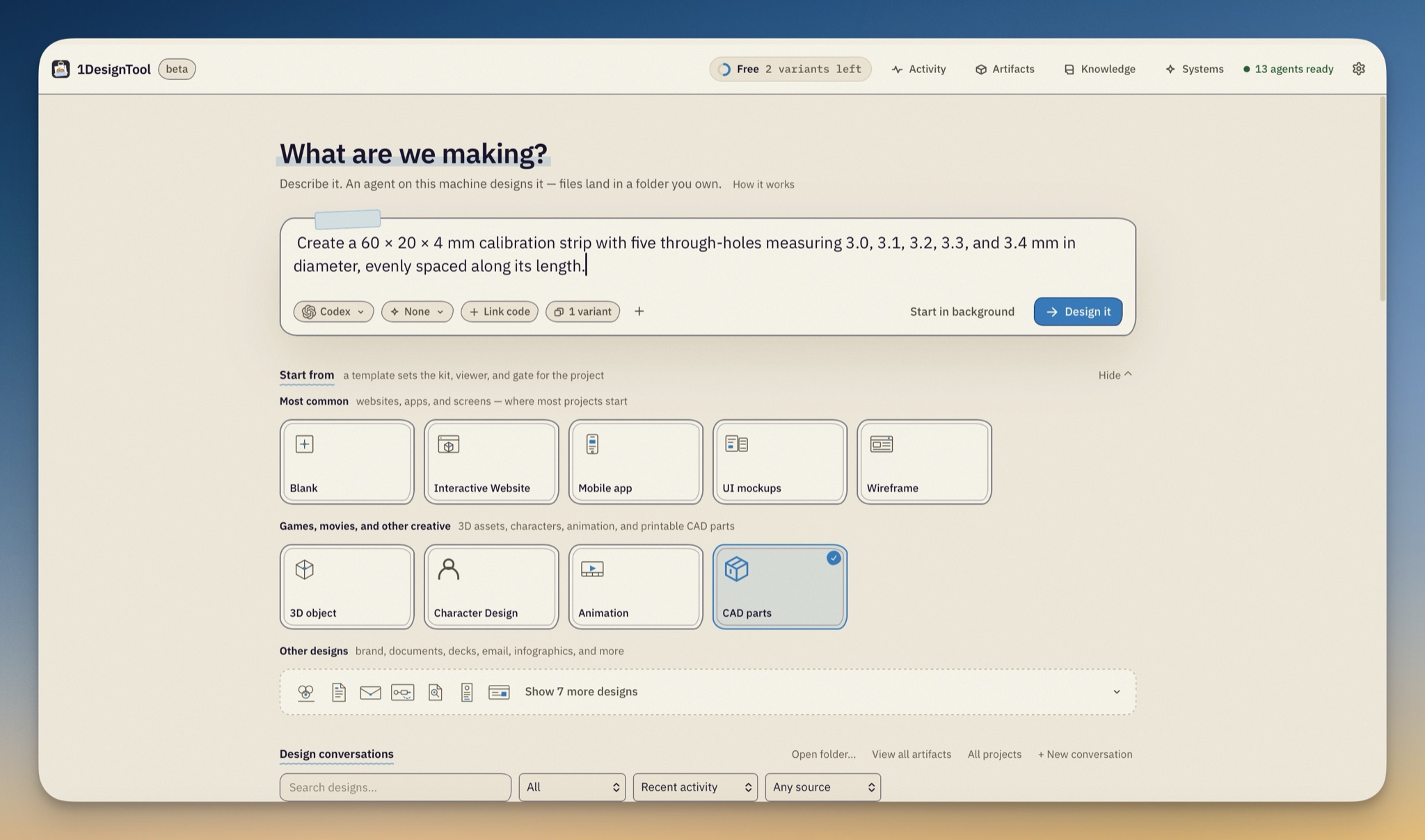
CAD parts sits on Home in the Games, movies, and other creative row, next to 3D object, Character Design and Animation. Pick it and write the part the way you would describe it to someone at a workbench: "Create a 60 × 20 × 4 mm calibration strip with five through-holes measuring 3.0, 3.1, 3.2, 3.3, and 3.4 mm in diameter, evenly spaced along its length."
The template works in millimetres throughout, and the result is parametric — a model.js that produces the solids, not a mesh someone sculpted. That is what makes the next step possible.
Adjust the dimensions, then commit
The workspace's side panel is headed CAD parts and carries five tabs: Parameters, Parts, Printer, Examples and Code.
Parameters is where a part stops being a one-shot generation. Change a dimension and the model rebuilds in the viewer. When it is right, Commit saves a history entry you can come back to; Cancel restores the saved parameters. Until you commit, the export buttons stay disabled — you cannot accidentally ship an STL of a shape you were still fiddling with.
The viewer is built for inspection rather than presentation: fixed Front, Right, Top and Iso views, a Section Z slider to cut through the solid, an Explode slider for assemblies, Measure two points for checking a dimension you care about, and Reset view. The Parts tab lists each named solid with its volume in mm³, and the hardware fits are listed separately so you can ghost one and see where the screw actually goes.
Run the checks, and read what they did not check
This is the part that makes it useful rather than merely quick. The stage carries an honest banner — Unverified · run checks for this revision — until you run the gate, and then the panel fills in per-check results.
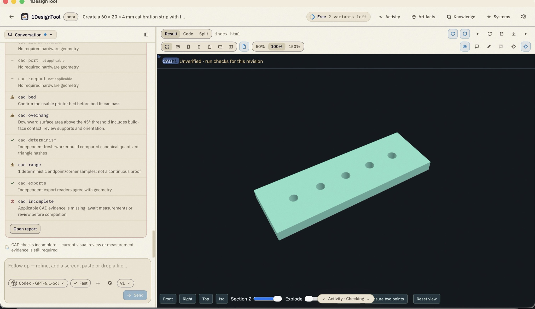
The gate runs fifteen rules grouped into technical, requirements and delivery concerns. It checks that the code runs and the parameters resolve, that the result is a closed solid inside its declared bounding box, that sampled wall thickness holds up, that declared clearances and keepouts are respected, that the part fits the printer bed, that overhangs past 45° are flagged for supports, that a fresh independent build produces the same geometry, and that an independent reader agrees with what the exports contain.
What matters as much is the vocabulary. A check can come back not applicable — cad.port and cad.keepout say "No required hardware geometry" on a part that declares none, rather than quietly passing. A check can come back incomplete: "Applicable CAD evidence is missing; await measurements or review before completion." The gate will hold a revision as unfinished rather than bless it, and Open report gives you the full evidence.
And the hard limit is stated rather than hidden: these are geometry and export checks. They are not a claim about physical fit or printability. A part that passes every rule still needs printing and testing against the real hardware. That is the honest position for a tool that has never touched your printer, and the workspace says so instead of implying otherwise.
Export for manufacturing, and open your slicer
Each named part exports as STL, STEP or 3MF from the Parts tab, and the whole assembly as Export assembly STEP — meshes for printing, STEP when something downstream needs real solid geometry.
The Printer tab holds a printer profile saved with the project, and asks you to confirm the usable bed before the bed-fit check can pass. Once files are written, each .stl or .3mf gets PrusaSlicer and OrcaSlicer buttons, so the path from "the part is right" to "the slicer is open" is one click rather than a trip through Finder.
Send a finished design to 1VideoTool
Separately, a design can now leave for 1VideoTool. A character still, a 2D puppet, a customized character GLB or a supported 3D scene can be sent as a portable asset.
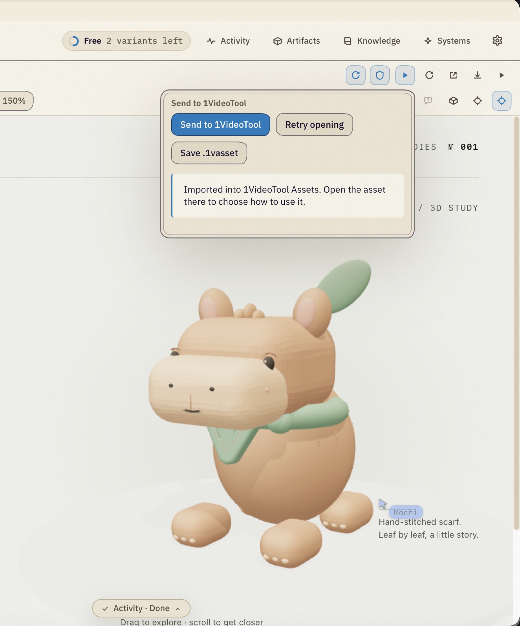
On desktop, Send to 1VideoTool captures the current design, publishes the bundle, opens 1VideoTool and then waits — it reports "Waiting for 1VideoTool to confirm import…" and only says "Imported into 1VideoTool Assets. Open the asset there to choose how to use it." once the other app has actually taken it. If it does not, you get Retry opening and Save .1vasset, and the bundle is remembered per project so a retry later still works. In the browser demo the same bundle downloads for manual import. No silent half-transfers.
One less trip for a finished design system
Smaller, but it removes a detour: the completed-design panel now carries Add Design System, which puts the system straight into Systems, and a download action for its tokens and DESIGN.md package. Last release put that export in the share menu; now it is also where you land when a design finishes.
Before vs after
| Before | Now | |
|---|---|---|
| Making a small functional part | Relearn a CAD program for an afternoon | Describe it in millimetres and adjust parameters |
| Changing a dimension | Hunt for the constraint that drives it | Edit the parameter, rebuild, commit |
| Knowing if it will print | Slice it and find out | Bed, wall, overhang and clearance checks first |
| What "passed" means | Whatever you assumed | Named rules, with the not-applicable and incomplete ones shown |
| Getting to the slicer | Export, find the file, open the app | PrusaSlicer or OrcaSlicer from the exported file |
| Moving a design to video | Export, locate, import by hand | Send, and wait for a confirmed import |
Who benefits most
People who print functional parts, not models. Brackets, spacers, mounts and clips are mostly dimensions and tolerances. That is exactly the part of CAD that a parametric description handles well.
Anyone who prints rarely enough to forget the software. The cost of an occasional part is almost entirely relearning the tool. Describing it removes that cost without removing the control, because the parameters are still yours to pull.
People who already design characters and scenes here. The 1VideoTool hand-off means a design that is finished in one app arrives in the other as an asset, with a confirmation rather than a hopeful file copy.
Try it
Pick CAD parts on Home and describe something you have actually needed — a calibration strip is a good first one, because you can measure the result. Adjust the parameters until the dimensions are right, run the checks, read what the gate says it did not verify, and then print it and find out. The tool will get you to a credible part quickly; the hardware still gets the final word, and this release is careful not to pretend otherwise.